Homepage > Digital servo controllers > TG Power
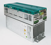
TG Power
Properties of TGPower
- Direct connection to an ordinary power supply (3x230V to 3x480V)
- Direct connection to a special power supply (3x48 až85 V, 3x115-230V)
- Built in anti-interference filter
- Control of the motor holding brake
- A built in internal brake resistor (with the ability to connect an external one)
- Interpolation (linear or spline)in a positioning controller
- Communicates via a CAN bus-protocol CANopen
- Communicates via a network bus with an EtherCAT protocol
- Digital inputs for capturing fast actions occurring at the same point in time
- Reduced loss due to the new space vector modulation (SVM)
- CE, UL, and c UL certificate
- Input for the blocking of repeated running for the safety of personnel, category 4 according to ČSN EN 954-1 a ČSN EN 61508
Feedback
- Resolver EnDAT (single-turn or multi-turn)
- Hiperface (single-turn or multi-turn)
- A sensor with sincos signals
- An Incremental sensor with commutative signals
- The possibility to simultaneously connect two sensors (comcoder)(e.g. resolver and sincos)
Control
- Current control – used only for current control
- Speed control – used for current and speed control
- Position control – used for current, speed and position control
TGP control (same for all models)
| Digital inputs |
| Enable (blocking off control circuits) |
| Lock (blocking off the power supply for IGBT modules rousers) |
| EN-Brake releasing of elmag. Brake (release elmag. brake) |
| 5 programmable digital inputs (e.g. position lock) |
| Digital outputs |
| Relay READY |
| Relay for locking of the power supply |
| 2 programmable outputs |
| Communication |
| RS232 Service channel for adjusting all parameters(applicable in all models) |
| USB Service channel for adjusting all parameters(applicable in all models) |
| CAN Real time motion control through the CANbus |
| EtherCat Real time motion control through the network bus EtherCat |
| EtherCat Real time motion control through the network bus EtherCat |
Modules TGP can be ordered with these communication cards
CAN – Communication through CAN bus
ETH – Communication through EtherCat
UNI – Communication through CAN busor EtherCat
SSI - Communication through a fast serial interface with SSI protocol
Technical data for models 3x48-230V
| Description | TGP_A310 | TGP_E305 | |
| DIM | 10A/10A/10A | 5A/5A/5A | |
| Number of axis | 3 | 3 | |
| Rated supply voltage | VAC | 3(1)×44–100 V/45–65 Hz | 3(1)×104–276 V/45–65 Hz |
| Rated installed load for S1 operation | kVA | 3 | 6 |
| Rated DC link voltage | VDC | 60–130 | 150–360 |
| Rated output current axis 1 (+/- 3%) | Arms | 10 | 5 |
| Rated output current axis 2 (+/- 3%) | Arms | 10 | 5 |
| Rated output current axis 3 (+/- 3%) | Arms | 10 | 5 |
| Peak output current axis 1 (+/- 3%) | Arms | 20 | 10 |
| Peak output current axis 2 (+/- 3%) | Arms | 20 | 10 |
| Peak output current axis 3 (+/- 3%) | Arms | 20 | 10 |
| Max. continuous sum current (cooling) | Arms | 20 | 15 |
| Rated load of internal regen circuit | W | 66 | 66 |
| Peak power regen circuit (ext) | W | 200 | 400 |
| Peak power regen circuit | kW | 800 | 1500 |
| Width | mm | 114 | |
| Height | mm | 241 | |
| Depth with connectors | mm | 255 (300) | |
Technical data for models 3x230-480V
| Description | TGP_S120 | TGP_S315 | TGP_S310 | TGP_S315 | |
| DIM | 20A | 10A/15A | 10A/10A/10A | 10A/10A/15A | |
| Number of axis | 1 | 2 | 3 | 3 | |
| Rated supply voltage | VAC | 3×207–528 V/45–65 Hz | |||
| Rated installed load for S1 operation | kVA | 14 | 14 | 14 | 14 |
| Rated DC link voltage | VDC | 290–690 | |||
| Rated output current axis 1 (+/- 3%) | Arms | 20 | 10 | 10 | 10 |
| Rated output current axis 2 (+/- 3%) | Arms | – | 15 | 10 | 10 |
| Rated output current axis 3 (+/- 3%) | Arms | – | – | 10 | 15 |
| Peak output current axis 1 (+/- 3%) | Arms | 40 | 20 | 20 | 20 |
| Peak output current axis 2 (+/- 3%) | Arms | – | 30 | 20 | 20 |
| Peak output current axis 3 (+/- 3%) | Arms | – | – | 20 | 30 |
| Max. continuous sum current (cooling) | Arms | 20 | 20 | 20 | 20 |
| Rated load of internal regen circuit | W | 200 | 200 | 200 | 200 |
| Peak power regen circuit (ext) | W | 1500 | 1500 | 1500 | 1500 |
| Peak power regen circuit | kW | 6,5–27 | |||
| Width | mm | 158 | |||
| Height | mm | 378 (472) | |||
| Depth with connectors | mm | 235 | |||

